
Blog · Electrical & home automation
Electrical panel, phase balancing and KNX home automation: the engineer's guide for your villa in Marrakech
In a high-end villa, the electrical installation is the most heavily used network and the least visible one. VRF air conditioning, induction hob, pool pump, water heater, architectural lighting, home automation: everything starts from the same panel. Badly designed, it means nuisance tripping, overheating cables, incomplete protection of people and a home automation system nobody can maintain. Well designed, you never notice it.
This guide sets out the method an engineer should follow to design, wire and test a villa's electrical panel: load assessment, phase balancing, earthing, residual current protection, surge protection and KNX architecture. It is written for owners, investors and Moroccans living abroad who want to check what they are handed over, not just take it on trust.
1. The load assessment: where everything starts
Before drawing a single circuit, the engineer draws up the load assessment: a list of every appliance, its rated power, its supply (single-phase 230 V or three-phase 400 V) and how likely it is to run at the same time as the others. This document sets the supply capacity to request from the utility, the rating of the main switching device, the size of the supply cable and the number of rows in the panel.
Installed load and maximum demand
The installed load is the sum of all circuits. The maximum demand applies two factors to it: the utilisation factor (a 1.5 kW motor does not always run at full load) and the diversity factor (nobody cooks, washes and tumble-dries in the same minute). The assessment must be written out circuit by circuit and handed to the owner.
Single-phase or three-phase?
As soon as a villa has VRF/VRV air conditioning, a sizeable pool pump, an induction hob and an electric water heater, a 230/400 V three-phase supply is generally the right choice: it spreads the load over three conductors, reduces cable sizes and directly supplies three-phase outdoor units and motors. In return, it brings a constraint that many installers overlook: phase balancing.
2. Designing the panel: layout, protection, cable sizes
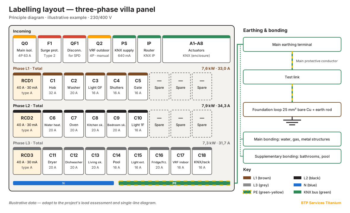
A villa panel reads like a drawing: from top to bottom, the incoming supply and main protection, then the groups of circuits, each under its own residual current device. We work with modular components from recognised ranges such as Schneider Electric, Hager or Ingelec. The brand matters less than consistency: one range per panel, suitable busbars, and a breaking capacity that matches the short-circuit current at the point of installation.
Typical layout of a three-phase villa panel
- Row 1 – incoming: 4-pole main isolator, surge protective device with its disconnector, protection of three-phase circuits (VRF outdoor unit), KNX bus power supply.
- Rows 2 to 4 – one group per phase: a 30 mA RCD at the head of the row, followed by the miniature circuit breakers of the circuits it protects.
- Home automation enclosure or rows: KNX actuators, line coupler or IP interface, gateways (VRF, DALI).
- Main earthing terminal and neutral bars, labelled, at the bottom.
Cable sizes and ratings: the pairs to respect
A conductor's cross-section is chosen according to the rating of the breaker protecting it, the installation method and the length (voltage drop). Common copper pairs in a dwelling:
| Circuit | Copper size | Breaker | Note |
|---|---|---|---|
| Lighting | 1.5 mm² | 16 A | Limited number of lighting points per circuit |
| 16 A sockets | 1.5 mm² | 16 A | 8 outlets maximum |
| 16 A sockets | 2.5 mm² | 20 A | 12 outlets maximum |
| Washing machine, dishwasher, oven, tumble dryer | 2.5 mm² | 20 A | Dedicated circuit |
| Electric water heater | 2.5 mm² | 20 A | Dedicated circuit, can be controlled by KNX |
| Single-phase hob | 6 mm² | 32 A | Or 2.5 mm² / 20 A three-phase if the hob allows it |
| Roller shutters, gate | 1.5 mm² | 16 A | Controlled by a KNX actuator |
| VRF/VRV outdoor unit | Per manual | Per manual | Rating and protection type specified by the manufacturer |
For long runs (pool house, garden lighting, gate at the end of the plot), the voltage drop is checked and the cable upsized where necessary: a correctly protected but overly long cable may not allow the breaker to trip on a short circuit.
3. Balancing three-phase loads: method and worked example
In a three-phase supply, each single-phase circuit is connected between one phase (L1, L2 or L3) and neutral. When circuits are connected as they come, the kitchen and the laundry often end up on the same phase. The result: one overloaded phase, a main breaker that trips while the other two phases are almost idle, a more heavily loaded neutral and electronic equipment that suffers from voltage fluctuations.
The method
- List every single-phase circuit with its design load.
- Set aside three-phase loads (VRF outdoor unit, three-phase pump or motor): by design they load the three phases evenly.
- Distribute the large loads first (hob, water heater, tumble dryer, oven) across three different phases.
- Fill in with medium then small circuits, aiming for the same load on each phase.
- Separate loads that run together: washing machine and dryer on two different phases, hob and oven too.
- Calculate the imbalance: (Imax − Iaverage) / Iaverage. Good-practice target: below 10%.
Worked example (typical villa, illustrative data)
Two-storey villa of about 300 m², 230/400 V three-phase supply. 18 single-phase circuits totalling 22.8 kW of installed load; the three-phase VRF outdoor unit is dealt with separately. Simplified calculation with cos φ = 1 and no diversity factor, to illustrate the distribution.
| Distribution | L1 | L2 | L3 | Imbalance |
|---|---|---|---|---|
| "As they come" (kitchen on L1, laundry and water heater on L2, the rest on L3) | 10.3 kW · 44.8 A | 8.3 kW · 36.1 A | 4.2 kW · 18.3 A | 35.5% |
| Balanced (distribution shown in the diagram above) | 7.6 kW · 33.0 A | 7.9 kW · 34.3 A | 7.3 kW · 31.7 A | 4.0% |
With the same total load, the first distribution puts 44.8 A on L1: the most heavily loaded phase reaches the threshold of the main device well before the other two. The second leaves the same margin on every phase and cuts the imbalance by a factor of almost nine.
4. Earthing and equipotential bonding
Residual current protection only protects people if the earth electrode is good. It is the most important part of the installation and the easiest to get wrong, because it is buried.
The earth electrode
- Foundation earth loop: a bare 25 mm² copper conductor laid at the bottom of the foundation trenches, under the blinding concrete, before the footings are poured. It is the best solution in new construction, and it cannot be added afterwards.
- Earth rods as a complement or alternative, driven vertically, in sufficient number to reach the target value.
- Earthing conductor from the electrode to the test link, then the main protective conductor to the panel's earth terminal.
- Test link, accessible and removable: it isolates the electrode so it can be measured at handover and during periodic inspections.
Main equipotential bonding
It connects to the main earthing terminal every metal part entering the building: water and gas pipes, metal air-conditioning ducts, accessible metal structures and, where accessible, the concrete reinforcement. The aim is that no dangerous voltage can appear between two parts touched at the same time.
Supplementary bonding: bathrooms and pool
In each bathroom, supplementary bonding connects the metal pipes, the metal bath or shower tray, metal door frames and the protective conductors of the room's circuits. In a pool, the metal parts (ladder, embedded fittings, lights, accessible reinforcement) are connected by dedicated equipotential bonding. Its absence is one of the serious defects we record during inspections, as in finding F-9 of our sample inspection report.
5. 30 mA RCDs and surge protection
Choosing the right type of RCD
- Type AC: detects only sinusoidal alternating fault currents. It is less and less suited to today's appliances.
- Type A: also detects pulsating DC fault currents. It is required for the hob and the washing machine, and it is the default choice we recommend for the whole villa.
- Type F: designed for single-phase variable-speed appliances and more resistant to nuisance tripping (freezer, variable-speed pump).
- Type B: for some three-phase equipment with power electronics, as specified by the manufacturer (drives, some charging points or inverters).
The rating of each RCD (40 A, 63 A) is checked against the sum of the circuits it protects, not chosen out of habit.
Surge protection: when and how
A villa with home automation concentrates equipment that is sensitive to overvoltage: KNX modules, air-conditioning control boards, internet router, alarm, CCTV. A type 2 surge protective device at the head of the panel limits surges coming from the network. Its value is assessed case by case (overhead or underground supply, site exposure, value of the equipment), but for a villa fitted with KNX and VRF, we recommend it every time.
6. KNX home automation: architecture, bus and actuators
KNX is an open international standard (ISO/IEC 14543-3): hundreds of manufacturers make compatible devices, all programmed with a single software tool, ETS. That is what sets it apart from proprietary systems: in ten years' time, another integrator can take over your installation, provided the project file is available.
The principle: separating control from power
In a conventional installation, the switch directly breaks the lamp's 230 V. In KNX, push-buttons, detectors and thermostats are sensors connected to a low-voltage bus. They send telegrams to actuators in the panel, which switch the power circuits. One control can therefore drive a light, a scene or a whole zone without any rewiring.
Bus topology
- Medium: KNX-certified twisted-pair bus cable (YCYM or J-Y(St)Y 2×2×0.8 mm²), green, supplied at safety extra-low voltage (about 30 V DC).
- Line: up to 64 devices per segment, supplied by a dedicated KNX power supply (640 mA is common in a villa).
- Areas and couplers: lines are grouped into areas by line couplers, or by IP routers that use the Ethernet network as the backbone.
- Addressing: each device has a physical address (area.line.device, e.g. 1.1.12); functions are linked by group addresses.
- Wiring: line, tree or star, never a loop, and no terminating resistor.
Choosing the actuators
- Lighting: switch actuators rated for the inrush current of LED drivers (capacitive loads), universal dimmers, or a KNX-DALI gateway for dimmable architectural lighting.
- Roller shutters and blinds: shutter actuators with travel-time measurement, percentage positioning and wind protection linked to a weather station.
- VRF/VRV air conditioning: a KNX gateway dedicated to the manufacturer's system, reporting temperatures, modes and faults, and allowing room-by-room control from KNX thermostats.
- Water heater, pool filtration, irrigation: time switching and load shedding during high consumption.
- Security: integrated opening, presence, flood and smoke detectors, presence simulation, link with the alarm panel.
- Supervision: visualisation on a screen and smartphone, secure remote access (KNX Secure, VPN).
7. What must be planned during the structural works
A well-designed KNX system and panel are prepared before the slabs are poured and the walls built. Making up for an omission later means chasing a finished wall or, worse, core-drilling a load-bearing slab.
- Panel recess: location, dimensions and depth of the panel and communications enclosure recess, with conduits running in from the utility's meter box.
- Dedicated conduits for the KNX bus, separate from power conduits, from the panel to each floor and zone.
- Deep flush boxes where push-buttons, thermostats and detectors will go.
- Outdoor links: VRF outdoor unit, pool plant room, gate, garden lighting.
- Foundation earth loop laid before the footings are poured, with its riser to the test link.
This anticipation of networks within the structure will be covered in a dedicated article on plumbing and electrical pre-installation.
8. Tests before energising
A panel is not finished when it is wired, but when it has been measured. The minimum list to insist on:
- Continuity of protective conductors and equipotential bonding.
- Insulation resistance of every circuit (tested at 500 V DC, minimum 1 MΩ per IEC 60364-6).
- Earth electrode resistance, measured with the test link open.
- Test of every RCD: tripping current and time measured with an instrument, not just with the test button.
- Check of terminal and busbar tightening, and of phase/neutral polarity.
- Measurement of phase currents under real load to confirm the balancing.
- Complete panel labelling, matching the single-line diagram.
- Handover file: load assessment, single-line diagram, labelling plan, test reports and, for home automation, the ETS project file.
Frequently asked questions
Does a villa in Marrakech need a three-phase supply?
It is not mandatory, but as soon as a villa has VRF/VRV air conditioning, a pool, an induction hob and an electric water heater, a 230/400 V three-phase supply is generally the most suitable solution. It spreads the load over three conductors and supplies three-phase equipment, provided the circuits are rigorously balanced across the phases.
Why does my RCD trip for no apparent reason?
The most frequent causes are the accumulation of permanent leakage currents from electronic appliances on a single RCD, an unsuitable RCD type (AC instead of A or F), moisture in an outdoor box or an emerging insulation fault. Spreading electronic loads across several RCDs and measuring the insulation of each circuit makes it possible to find the cause.
What is phase balancing and how is it checked?
It is the distribution of single-phase circuits across phases L1, L2 and L3 so that each carries a similar load. It is checked on the load assessment, then by measuring the current on each phase under real load. Good practice keeps the gap between the most loaded phase and the average below 10%.
What earth resistance should be targeted?
The protection condition requires R × IΔn ≤ 50 V. With a 500 mA main device, the resistance must be below 100 Ω. In practice, a much lower value is targeted, ideally obtained with a foundation earth loop laid before the footings are poured, and measured at the test link.
Is a surge protector mandatory in a villa?
Whether it is mandatory depends on site exposure and the type of supply, but it is strongly recommended in a villa with home automation: a type 2 surge protective device at the head of the panel protects KNX modules, air-conditioning control boards and security equipment from overvoltage.
KNX or wireless home automation: which is better for a new villa?
For new construction, wired KNX is the most robust choice: an open standard, independent of any single manufacturer, with no batteries and no reliance on Wi-Fi, and any certified integrator can take it over using the ETS project file. Wireless remains useful in renovation or to extend an existing installation.
When should KNX home automation be planned?
From the design stage, and at the latest before the structural works: the panel location, bus conduits, deep boxes and outdoor links are reserved before the slabs are poured and the walls built. Adding KNX afterwards means chasing walls and making compromises.